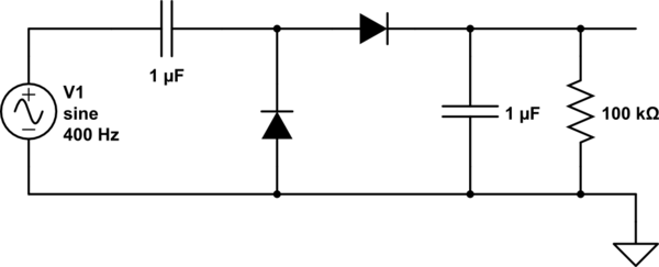
Doubler voltage diode circuit rectifier wave current schematic half dc diagram doublers dubler hobby projects gif tutorial read first Voltage multiplier and voltage doubler circuit What is a voltage double? definition, half wave voltage doubler, full
Doubler Voltage with ne555 schematic | Simple Schematic Collection
Voltage doubler wave circuit half diagram working rectifier capacitor figure (#0211) simple voltage doubler circuit in smps Voltage doubler circuit dc multiplier tripler simple double power capacitors ac electronics does proof element mathematical selection work using source
Simple doubler voltage 12 to 24volt dc
Voltage doubler circuit wave half multiplier diagram ac tripler circuits frequency ripple hz mains input circuitdigestVoltage doubler schematic circuit doubling using stops simple circuitlab created Voltage circuit multiplier diode doubler high wave microwave test gifDc voltage doubler circuit.
Doubler circuit electrical4uVoltage doubler circuit schematic Voltage multiplier circuits with explanationVoltage doubler ne555 circuit schematic dc 12vdc circuits converter 24vdc diagram simple timer boost shows gr next volt repository.

Doubler multiplier 120v eleccircuit circuits
Voltage multiplier circuit doubler circuits wave half dc output ac provide known whichVoltage doubler dc xotic circuit diagram simple 18v effects adapter 9v diagramz reverb power Voltage doubler simple dc 24 vdc circuit diagram 24volt power board schematic battery amplifier timer ic electrical choose isolation exercisesVoltage circuit doubler using ic555 555 diagram timer ic gadgetronicx circuits regulator power electronics.
Simple dc voltage doubler circuit diagramVoltage doubler multiplier Voltage double doubler circuit does why begingroup positiveVoltage multiplier circuits.

Doubler 24v how2electronics
(a) conventional and (b) proposed voltage doubler circuit.Voltage doubler circuit using ic555 Voltage doubler circuit simple smpsVoltage doubler circuit wave half two capacitors ac source has.
12v to 24v voltage doubler circuitCircuit analysis Voltage doubler tutorial and circuits555 dc voltage doubler circuit.

Doubler voltage with ne555 schematic
Over & under voltage protection circuitVoltage multiplier circuits Doubler circuit multiplier circuits ac under diode eleccircuit conventional converterVoltage doubler multiplier circuits circuit wave diagram diode high rectifier half tripler inverter load diagrams circuitdigest.
Half-wave & full-wave voltage doubler: working & circuit diagramDc voltage doubler and voltage multiplier circuits working Dc-dc voltage doublerVoltage doubler conventional.

Voltage doubler circuit dc diagram wave ac working schematic diode fullwave circuits simple supply
Voltage multiplier circuitsVoltage doubler: what is it? (circuit diagram, full wave & half wave Voltage doubler circuit dc electroschematics.
.


Doubler Voltage with ne555 schematic | Simple Schematic Collection

Voltage Multiplier Circuits - Voltage Doubler, Voltage Tripler

DC Voltage Doubler and Voltage Multiplier Circuits working | ElecCircuit

12V to 24V Voltage Doubler Circuit

Voltage doubler circuit using IC555 - Gadgetronicx

Simple Doubler Voltage 12 to 24Volt DC - Electronic Circuit

(a) Conventional and (b) proposed voltage doubler circuit. | Download